Part2.2 documents how I managed to get sensor reading from IMU. The complete code can be found in my Github. Note that this post is a legacy post documenting how I tried to get data from IMU using Arduino.
Orientation is calculated from IMU readings. In this project, I aim to use a quaternion Kalman Filter to perform sensor fusion. To test the performance of the Kalman Filter, I intend to run a simulation on Matlab that receives sensor data from Arduino via serial communication. I will write down the detailed steps below.
Part 2.1 Get Data from MPU9250 Sensor Module.
As innovation is not the primary interest of this project, I choose the popular MPU9250 from Invensense as my 9DOF IMU to get the orientation of the quadcopter. The supposed way is to buy the sensor, solder it onto a PCB with your chosen Microcontroller and progarm from there. Since at current stage, I am more interested to testing the software instead of building the hardware, an existing sensor module is chosen.
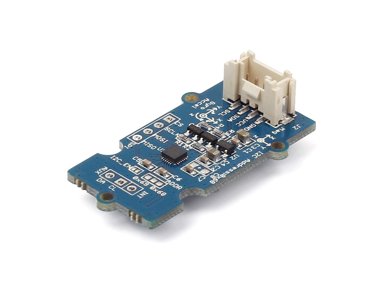
I bought this sensor module from SeeedStudio. The connector on the module breaks out MPU9250's I2C interface, allowing it to communicate with most Microcontroller directly. I use Genuino 101 in this case.
The connection is shown in the picture below. Red wire is 3.3V power input. Black wire is the ground. White wire is I2C SDA(data) and lastly the yellow wire is I2C SCL(clock). Using existing sensor module makes prototyping super fast and easy especially when it has a Linear voltage regulator in-built which allows this module to be powered by both from 1.8V-6V.

SeeedStudio also offers a ready-to-use Arduino library to get sensor data. Convenient as it is, there are slight mistakes in the library offered and it does not expose some important functions for this project.
Here are the details, if you open up the MPU9250.h file inside the library, you will see these section of code:
#define MPU9250_RA_CONFIG 0x1A
If you check against the register map of MPU9250 provided by Invensense, you will find that the register address does not correspond to the code above. There is no register with address 0x21 and 0x22 and the names for registers with address from 0x1C to 0x1F are wrong, Regardless of the reason behind this deviation, I modified the file according to the register map provided by Invensense.
#define MPU9250_RA_CONFIG 0x1A
#define MPU9250_RA_GYRO_CONFIG 0x1B
#define MPU9250_RA_ACCEL_CONFIG 0x1C
#define MPU9250_RA_FF_THR 0x1D
#define MPU9250_RA_FF_DUR 0x1E
#define MPU9250_RA_MOT_THR 0x1F
#define MPU9250_RA_MOT_DUR 0x20
#define MPU9250_RA_ZRMOT_THR 0x21
#define MPU9250_RA_ZRMOT_DUR 0x22
#define MPU9250_RA_FIFO_EN 0x23
#define MPU9250_RA_I2C_MST_CTRL 0x24If you check against the register map of MPU9250 provided by Invensense, you will find that the register address does not correspond to the code above. There is no register with address 0x21 and 0x22 and the names for registers with address from 0x1C to 0x1F are wrong, Regardless of the reason behind this deviation, I modified the file according to the register map provided by Invensense.
The result is as follows.
#define MPU9250_RA_CONFIG 0x1A
#define MPU9250_RA_GYRO_CONFIG 0x1B
#define MPU9250_RA_ACCEL_CONFIG 0x1C
#define MPU9250_RA_ACCEL_CONFIG2 0x1D
#define MPU9250_RA_LP_ACCEL_ODR 0x1E
#define MPU9250_RA_WOM_THR 0x1F
#define MPU9250_RA_FIFO_EN 0x23
These registers are important to me as configuring these registers control the output data rate of the sensors as well as the range of the sensors. After editing the MPU9250.h, I have to modify the MPU9250.cpp as well to add necessary functions.
For example, I have added the following functions, allowing me to set accelerometer's output data rate.
//ACCEL_CONFIG2 register
uint8_t MPU9250::getAccDLPFMode() {
I2Cdev::readBits(devAddr, MPU9250_RA_ACCEL_CONFIG2, 2, 3, buffer);
return buffer[0];
}
void MPU9250::setAccDLPFMode(uint8_t bandwidth) {
I2Cdev::writeBits(devAddr, MPU9250_RA_ACCEL_CONFIG2, 2, 3, bandwidth);
}
void MPU9250::setAccFchoice(uint8_t destination){
I2Cdev::writeBits(devAddr, MPU9250_RA_ACCEL_CONFIG2, 3, 1, destination);
}
Note that the third and fourth argument in the readBits function indicates the start bit and the bit length respectively. For example, if in register with address 0x1A which has 8 bits, bits[3:1] (bits 3,2,1) determines a certain property, if you want to change that property, you have to set both third and fourth argument to 3, meaning the part of of register to be configured starts from bit 3 and has a length of 3 bits. More details can be found in register map of MPU9250.
The modified library can be found in my Github, which also contains my Arduino sketch to get sensor data. To save time, I did not write the Arduino sketch from scratch but instead modify from the example given by the Seeedstudio. Once one installs the library, the original example sketch can be found in File\Examples\Grove_IMU_9DOF_9250 in arduino IDE.
In the setup() function, I added these functions for necessary configurations. Now both gyro and accelerometer have output data rate of 1000hz while magnetometer has output data rate of 100Hz. The gyro measurement range is 500 degree per second. The accelerometer measurement range is remained as default which is 2g.
//set gyro output data rate to 1000hz
accelgyro.setGyroDLPFMode(1);
//set gyro output range to 500dps
accelgyro.setFullScaleGyroRange(1);
//set accel output data rate to 1000hz
accelgyro.setAccDLPFMode(1);
//set i2c bypass enable pin to true to access magnetometer
I2Cdev::writeByte(0x68, MPU9250_RA_INT_PIN_CFG, 0x02);
delay(10);
// set mag to continuous measurement mode.
I2C_M.writeByte(MPU9250_RA_MAG_ADDRESS, 0x0A, 0x06);
//0x06 = 00000110 = continuous measurenment mode 2. 100Hz output data rate.
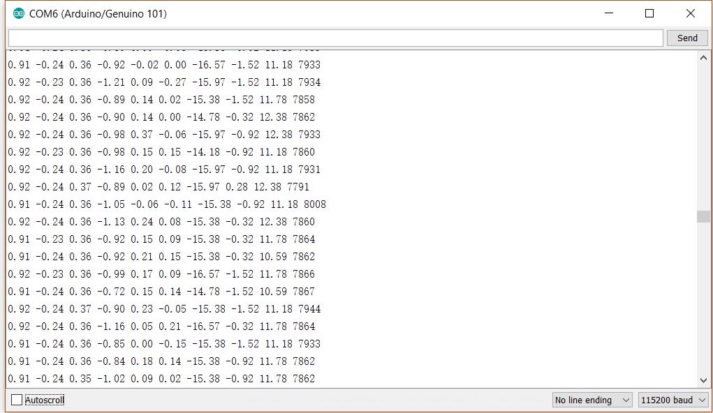
In loop() function, I changed the output format of the serial communication so that the data will be output in the following format
accX accY accZ gyroX gyroY gryoZ magX magY magZ timeElapsed
where accX means accelerometer's measurement in X axis and so on. In total,10 data are output within one execution of the loop and each data is separated by a blank space. Since Matlab receives serial communication data as character array, this format allows Matlab to convert data to numbers easily. The last data "timeElapsed" estimates the time interval between each gyroscope measurement by calculating the time taken for Arduino to execute one whole loop. Pseudocode at the btm is to illustrate the idea.
//get gyro data and calculate time spent for getting that data.
startTime = micros();
getGyro_Data();
getAcce_Data();
getCompass_Data();
publishdata();
endTime = micros();
elapsedTime = endTime-startTime;
However, The elapsed time calculated this way deviates from real value greatly if the rotation is fast. By right, since the data output rate is 1000hz, each data is only valid for 1/1000=0.001 second. An optimal system therefore has to be able to process data within 0.001 second so that it can be ready to receive the next measurement when it arrives. However, arduino is not fast enough and each iteration of the loop takes a lot longer to execute. Hence, when the arduino is ready to receive the next data, multiple sensor measurement have been bypassed. But for the purpose of continuity. I have to assume that each gyroscope measurement is valid for the whole duration of executing one iteration when in reality it is not the case especially if the sensor is rotating fast.That has potential to yield serious error in orientation calculation and it will be demonstrated in video to be uploaded in later post.
Anyway, the estimation should be accurate enough as long as the sensor is not rotated fast.
Some miscellaneous configurations and modifications are listed as follows.
- In the original example, getMotion9() is called in getGyro_Data(0 and get Accel_Data() functions. I changed the getMotion9() to getRotation() and getAcceleration() respectively to save time and also be more compact. (Both functions are provided by MPU9250 library)
- Before getting magnetometer measurement, dataready bit is first checked. If dataready bit equals to 0, meaning no new data is available, previous measurements are kept as the new measurement.
- I changed the magnetometer operating mode to continuous measurement mode in setup() as shown previously. The original example set the measurement mode as single measurement mode. Therefore, when Arduino wants to get magnetometer measurement, it has to first set the magnetometer to single measurement mode, asking the magnetometer to measure one set of data followed by returning back to power down mode. And during that duration, Arduino just sits idle and wait for magnetometer to finish measuring. The process to me wastes time. By setting the magnetometer in continuous measurement 2 where it measures data at a constant frequency of 100Hz, Arduino now only needs to check whether a data is available and get the data from magnetomer without having to set magnetometer operating mode and waiting idly in every iteration.
The result from the arduino sketch is demonstrated in the figure below. It shows that all 10 data are output correctly. The elapsedTime as shown is approximately 8ms, 8 times slower than the gyro measurement frequency.
Getting data from MPU9250 is now concluded. The next part will be about Quaternion Kalman Filter.
No comments:
Post a Comment