This post documents how to get data from MPU9250 using interrupt. The detailed code can be found in my Github. Note that in final implementation, the MCU reads data from MPU at a fixed frequency. Interrupt is actually not used. This post merely is for documentation purpose.
Therefore, with the new method, MPU9250 is programmed to send an interrupt to a GPIO pin of the STM32 microcontroller. When the microcontroller detects the interrupt, a data ready flag is set. The flag is checked before the execution of a new iteration. If the flag is set, STM32 will then fetch data from MPU9250 and perform sensor fusion. If the flag is not set, STM32 will start a new iteration. This posts will briefly explain the procedure to implement the method proposed above.
First, the interrupt needs to be enabled in MPU9250. This is done by configuring the Interrupt Enablee Register (Register 56) of the MPU9250. By setting the last bit of this register to 1, the data ready interrupt is propagated to interrupt pin. Furthermore, Register Int Pin/Bypass Enable Configuration (Register 55) needs to be configured to set the property of the data ready interrupt. The description of the Register is summarized in figure below. This is from the Register Map of MPU9250 provided by Invensense.


My choice for the property of interrupt is highlighted in the figure above. Therefore, I have to set the value of this register to 0x00100010 (0x22). Bit[1] is set to 1 to allow me to access magnetometer as described in Part2.1. Bit[0] is reserved so it should not be changed.The original value of Bit[0] is 0. Setting of the register is done using the following code.

Code commented out at the bottom is the code used to send data via I2C in Arduino. Intuitively, since now the platform is STM32, corresponding STM32 peripheral library needs to be used instead. ST has provided the library named HAL. The initialization of HAL peripheral library is done by the auto code generation of STM32CubeMX so it can be used readily. So here the function HAL_I2C_Mem_Write is used to send the data to MPU9250 via I2C.
I have migrated the whole MPU9250 library I used before from Arduino to STM32 by rewriting all the I2C functions. To save time and work, majority of the original library code was deleted. Only those necessary functions that this project will use are saved. The migrated library can be found here and here.
The next step is to configure the GPIO pin of STM32 to serve as an interrupt detector. This is done again via STM32CubeMX.

As shown in the figure above, pin PF12 is configured as GPIO_EXTI12 which means PF12 is used to detect external interrupt. PF12 is chosen arbitrarily and it maps to the PIN named D8 on Nucleo. The next step is to navigate to configuration panel, select GPIO and configure the pin as shown in the figure below.

Then select NVIC and enable EXT1 line interrupt by checking it as shown in the figure below.

Then code generation of STM32CubeMX will automatically configure and enable the interrupt. However, user is still required to write the custom interrupt handler.
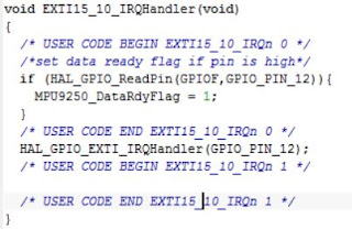
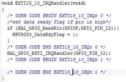
Interrupt handler is written in a file called stm32f4xx.c not main,c. The file is by default located in USER folder in IAR workspace. Inside this file there is a function called EXTI15_10_IRQHandler and this function is the interrupt handler of interrupt that happen on pin PF12. So when an interrupt happens on PF12, the MPU9250 data ready flag should be set to 1. This done by the following code.

Note that the variable MPU9250_DataRdyFlag is defined in main.c. Therefore, it should be declared "extern" in stm32f4xx.c as shown below so the compiler knows that this variable is the same variable used in main.c

The final step is to define data ready flag in main.c and check whether that is set at the start of every iteration of the main loop. This is demonstrated in the following figure.
So that concludes the steps needed to get data from MPU9250 by interrupt.
No comments:
Post a Comment