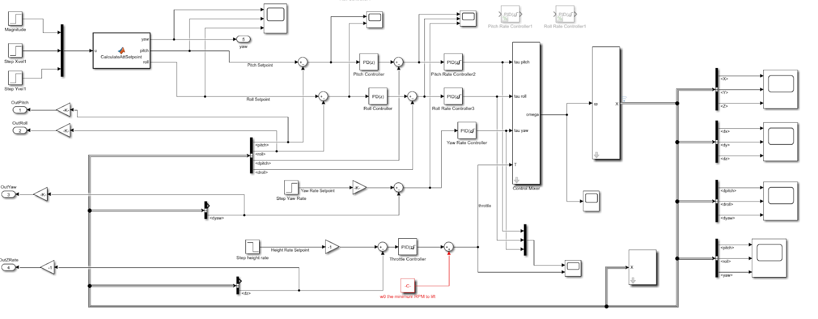
I created a Simulink in Matlab 2017b to test the controller structure before actual implementation. The Simulink model can be found in the github repository. Below is a screenshot of the model.
In order to run this model, one needs to download Peter Corke's robotics toolbox version 10.1. This toolbox will provide a quadrotor dynamics model as well as quadrotor plot for you to visualize the result of your controller.
As shown in the above figure, my controller has three loops. The inner-most loop controls quadcopter's attitude rate, the middle loop controls quadcopter's attitude while the outer-most loop controls quadcopter's velocity. In addition, quadcopter's height rate is controlled in a separate control loop. Simple PID controllers are used for all control loops and they are tuned using Simulink's control system tuner functionality.
Running this model will display a quadcopter taking off in response to a height rate command and later move horizontally in response to step velocity in both x and y direction. This shows that the controller works in simulation.
Initially as the model shows, I wanted to control quadcopter's velocity in global frame plus its yaw rate. However, I only had one single sensor, the IMU and thus could not accurately measure velocity in global frame. What the IMU can give me was just quadcopter's estimated attitude and attitude rate. Therefore, in actual implementation, I decided to simplify the controller into just two loops. The outer loop controls quadcopter's attitude and the inner loop controls quadcopter's attitude rate. For the same reason, I am unable to get accurate velocity measurement in z direction as well and thus unable to control quadcopter's height. In actual implementation, the height of the quadcotper is not controlled. The throttle of RC transmitter directly controls how fast the propeller should spin.
As a result, the RC transmitter will set the desired values of the following four quantities: throttle, yaw rate, pitch and roll.
Implementation of controller can be summarized in the below function screenshot.
bool Controller::RunAttCtrl(){ #if UAV_CONTROL_ATT // att controller mAttRateSetpoint.pitch = mAttController_pitch.GetDesiredAttRateSetpoint(mAttSetpoint.pitch, mCurAtt.pitch); mAttRateSetpoint.roll = mAttController_roll.GetDesiredAttRateSetpoint(mAttSetpoint.roll, mCurAtt.roll); // no need to control yaw angle #endif return true; } bool Controller::RunAttRateCtrl() { // attRate float rollThrust = mAttRateController_roll.GetDesiredMotorThrust(mAttRateSetpoint.roll, mCurAttRate.roll); float pitchThrust = mAttRateController_pitch.GetDesiredMotorThrust(mAttRateSetpoint.pitch, mCurAttRate.pitch); float yawThrust = mAttRateController_yaw.GetDesiredMotorThrust(mAttRateSetpoint.yaw, mCurAttRate.yaw); LOGI("Thrust: pitch: %f roll: %f yaw: %f height: %f\r\n", pitchThrust, rollThrust, yawThrust, heightThrust); float heightThrust = GetHeightThrustFromAccSetpointZ(mAccSetpoint.z); // get thrust from z accleration. // float heightThrust = mAccController_Z.GetOutput(mAccSetpoint.z, mCurAcc.z); mMotorCtrl.OutputMotor(pitchThrust, rollThrust, yawThrust, heightThrust); return true; }
In my code's main loop, the function RunAttCtrl() will first be called to calculate attitude rate setpoints from desired attitude and current attitude. Note that the current attitude is calculated by sensor fusion algorithm as mentioned in previous posts. Afterwards, the function RunAttRateCtrl() function will be called to calculate the desired motor thrust from desired attitude rate and current attitude rate given by gyroscope in IMU.
Note that the inner attitude rate control loop needs to run faster than the outer attitude control loop. The reason is that it takes multiple iterations of inner loop to follow one step attitude rate setpoint calculated by the outer attitude control loop. If both loops run at the same frequency, the whole system is likely to be stable as the outer loop already outputs a different setpoint before the inner loop could reach the previous setpoint. In my case, my outer attitude control loop runs at 20Hz while the inner attitude rate control loop runs at 100Hz.
One interesting realization I had during testing is that the frequency of inner attitude control loop needs to be high for quadcopter to fly. Initially, my inner attitude rate control loop ran at 50Hz and the quadcopter just could not fly stably no matter how I adjusted PID values. After I changed the inner loop's frequency to 100Hz, suddenly the quadcopter is able to fly. This shows the importance of the speed of inner attitude rate control loop. Arguably, the faster, the better. Unfortunately in my case, my sensor measurement frequency is capped at about 125Hz due to digital low pass filter I enabled to reduce noise. So 100Hz is almost as fast as I could get.
After the control loops calculate the desired pitch, roll, yaw and height thrust values, the last step is to combine them into PWM values for each motor. It turns out that a simple linear combination works as shown below.
After the control loops calculate the desired pitch, roll, yaw and height thrust values, the last step is to combine them into PWM values for each motor. It turns out that a simple linear combination works as shown below.
bool MotorCtrl::OutputMotor(float pitchThrust, float rollThrust, float yawThrust, float heightThrust)
{
    int motorPWM[4];
    if (mToClampThrust) {
        if (heightThrust > 800) heightThrust = 800; // clamp height thrust.
    }
    motorPWM[0] = (int) (-pitchThrust + rollThrust + yawThrust + heightThrust); // frontleft
    motorPWM[1] = (int) (-pitchThrust - rollThrust - yawThrust + heightThrust); // frontright
    motorPWM[2] = (int) (pitchThrust + rollThrust - yawThrust + heightThrust); // backleft
    motorPWM[3] = (int) (pitchThrust - rollThrust + yawThrust + heightThrust); // backright

    for (int i = 0; i < 4; ++i) {
        if (motorPWM[i] < UAV_MOTOR_MIN_DUTYCYCLE) {
            motorPWM[i] = UAV_MOTOR_MIN_DUTYCYCLE;
        } else if (motorPWM[i] > UAV_MOTOR_MAX_DUTYCYCLE) {
            motorPWM[i] = UAV_MOTOR_MAX_DUTYCYCLE;
        }
    }

    LOGI("motorPWM: 1 %d , 2 %d, 3 %d, 4 %d\r\n", motorPWM[0], motorPWM[1], motorPWM[2], motorPWM[3]);

#if UAV_ENABLE_MOTORS
    PWM_SetDutyCycle(PWM_CHANNEL_1, motorPWM[0]);
    PWM_SetDutyCycle(PWM_CHANNEL_2, motorPWM[1]);
    PWM_SetDutyCycle(PWM_CHANNEL_3, motorPWM[2]);
    PWM_SetDutyCycle(PWM_CHANNEL_4, motorPWM[3]);
#endif
    return true;
}
To decide whether to add or minus one particular thrust value for each motor, one needs to first define the coordinate frame of the quadcopter. In my case, I choose the frame as where x axis points to the forward direction of the quadcopter, y axis points to the left direction and z axis points to the top. In this case, if the quadcopter wants to move forward, the desired pitch value should be positive according to the right hand rule of rotation. A positive desired pitch value will yield positive pitchThrust and since the front two motors should spin slower for the quadcopter to pitch forward, pitchThrust should be deducted away from their motor PWM values. Similar logic could be applied to other thrust values for each motor.
No comments:
Post a Comment